Dwolson's 135gal Build

dwolson2

New member
Joined
Feb 11, 2011
Messages
378
Likes
1
Points
0
Location
Camarillo
#1
Well here is how it started out:
I am starting with a 48*24*28 reef ready tank. Converting the dual overflows into a coast to coast bean animal. Going to be a black background, black stand and canopy, and re do the door so it opens like a regular door instead of lifting up.


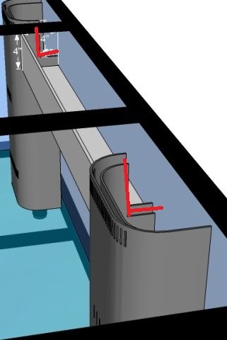
C2c test fitted and siliconed in as well as back glass painted black.Also notched out part of the dual overflows so the coast to coast will actually function.


Side view

Doors are cut, now to hang them and paint them.


And the inside painted:


Plumbing Done, front left, emergency and syphon

Front right return and wet:

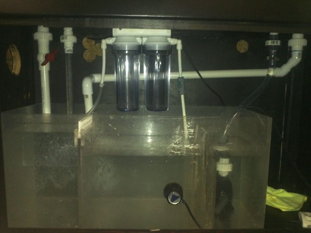
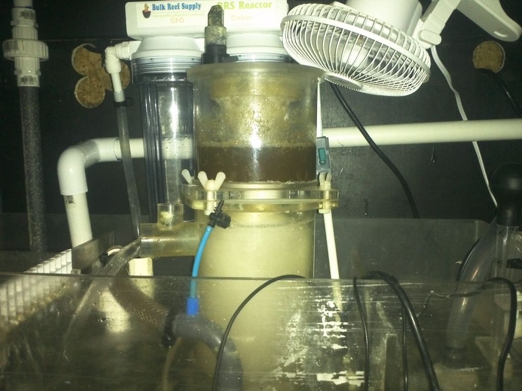
Plumbing underneath done brs reactor installed:

Apex temporarily installed(stopped working because I messed up the firmware update, but later fixed and reinstalled it)

And here it is reinstalled:

1st batch of rockwork and waiting to fill it with RODI:

And filled with RODI

Skimmer in place along with fan wired up:

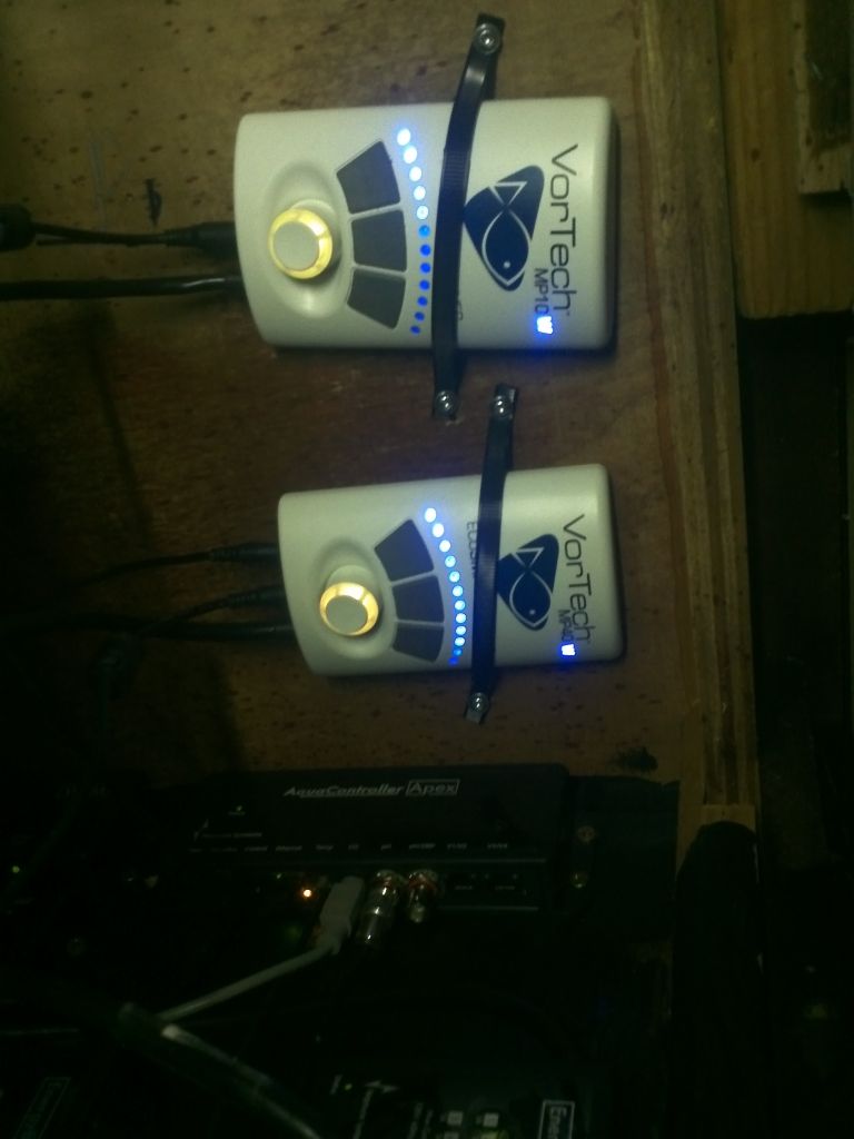
Vortech controllers mounted underneath the top of the stand, Velcro and zip tied:

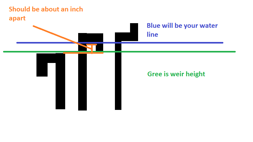
Although not in order this is how the plumbing is set up between the two overflows:

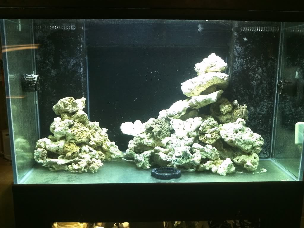
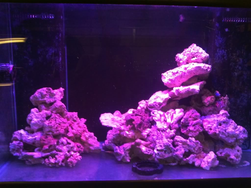
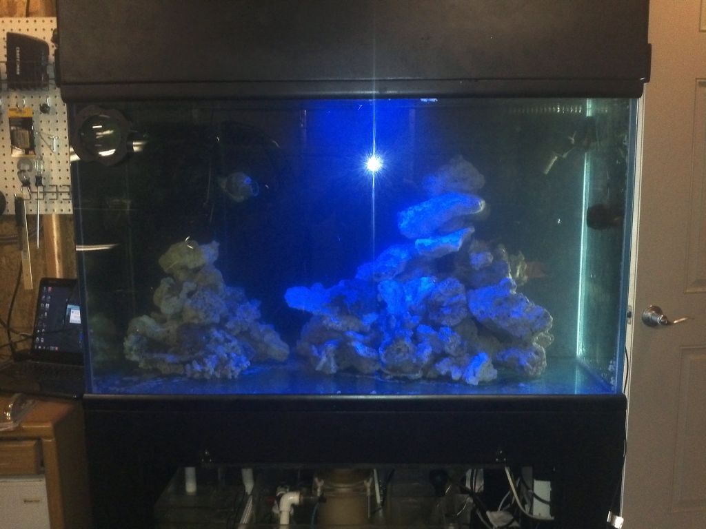
With new rock in the tank, still need help with aquascaping:

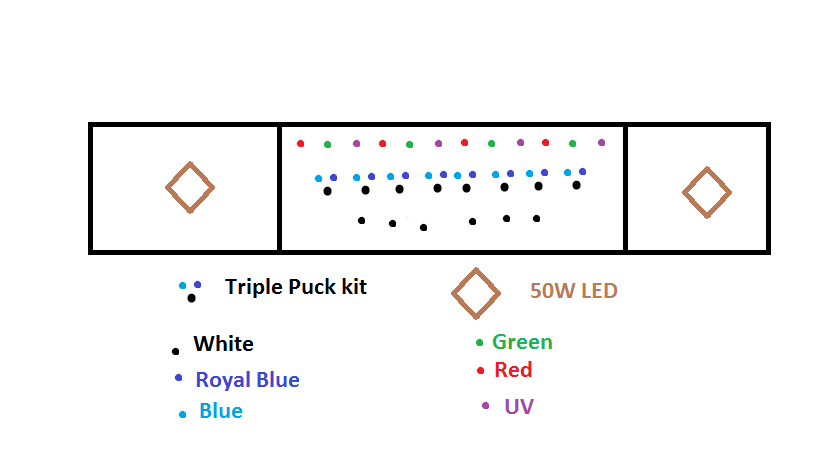
Proposed LED set up mock up:

Equipment list:
Apex(full) with 2 EB8s, break out box, WXM,Custom sump, DIY LED Lights, Apex, MP40, MP10, 2-6025's, Schuran Jetskim 150w/ Eheim 1260, ecoplus1056 for the return pump, ATO handled by apex with an aqualifter.
Intended list:
VDM to control the 50Wleds, 2 BRS dosing pumps(or BMT01), 2-50w LEDs and drivers
Possible over time:
Another mp40 or mp10 or put 2 tunze 6095s in the back.
Avast swabbie with skimmate locker
So officially the agreement with my wife is since I got to upgrade(coming from a 75) I dont get to set it up until we leave in May. SOOOO,I am curing my rocks, pulling every last piece of nutrients off of them(and there is a lot) making sure everything functions as it should until then, then when I set it up, remove the plumbing a few parts of electrical and the thing should go back together fairly simple. Thats the plan At least I get to look at a tank while I am waiting this way.
So this build is going to take a while, I only spend about 15min a day(after I get ready before I leave for work) on it, and there is only so much you can do. The plan when I set it up is going to be a mostly softie tank with LPS and although its TBD, a few tangs in the tank.
 

pgr11

Member
Supporter
Joined
Jul 26, 2011
Messages
11,011
Likes
92
Points
48
Location
Hesperia
#2
Very nice. Bummer you don't get to set it up completely until may. You will love the bean animal overflow drain setup. I used it on my tank and love it. Silent and your covered if a drain gets clogged. This indeed will be a slow build but I'm sure rewarding.
 

dwolson2

New member
Joined
Feb 11, 2011
Messages
378
Likes
1
Points
0
Location
Camarillo
#4
Very nice. Bummer you don't get to set it up completely until may. You will love the bean animal overflow drain setup. I used it on my tank and love it. Silent and your covered if a drain gets clogged. This indeed will be a slow build but I'm sure rewarding.
I have had it on two other tanks. I don't think I would set up another tank without it! I love the design!

Nice tank Rebuild... looking forward to see the completion.
Thanks as PGR said, its going to be a looooong build, but hopefully I will get it Just the way I want it.
 

dwolson2

New member
Joined
Feb 11, 2011
Messages
378
Likes
1
Points
0
Location
Camarillo
#7
I didn't think the black would look as good as it does. Nice looks great.
Lol, I'm glad you like it, I'm treating your old tank good :)
That tank looks sweet. Could you please explain the overflow setup. I think I get it, but I don't want to misunderstand it...
I will try to get better picture tomorrow morning, and explain it then. I've gotten a lot of comments to do just that.
 

dwolson2

New member
Joined
Feb 11, 2011
Messages
378
Likes
1
Points
0
Location
Camarillo
#8
So I’ve been asked to give a good description of the overflow and how it works.
Before I begin, I want to credit teslareef on rc for the CAD drawings.
How it works, it’s a bean animal design. The plumbing from left to right is Siphon, emergency, return, wet.

The siphon will be solid with water and have a valve to control flow through it. Since a siphon is the best way to move water and is absolutely silent, that’s takes the bulk of the water flow. Pumps fluctuate, so you couldn’t only have a siphon, because of that you have a wet stand pipe. The wet stand pipe takes any fluctuations that are in the flow. The last pipe is emergency, which will take flow in the event the wet or siphon become clogged. If the siphon or wet (when I install the airline piece in the cap) reach a certain level, they will turn into siphons a “flush” all the water into your sump.
That’s the basic design of the bean animal. Most of the time you see all of this done in one overflow box and in the back of the tank. Because I have a reef ready tank, with two overflows, I could have done a Herbie or leave the standpipe, but neither is perfect, and in my opinion far less superior to the bean animal(also I should note, bean animal took a herbie design and added an emergency, so although the herbie was really good, once the bean animal was made, it’s no longer the best )
How do I make dual overflows work as one was my new problem. A few solutions are to remove both overflows, put in a false wall all the way across making one big overflow (also taking away a lot of display area), I could have run a pipe from overflow to overflow in the display(which wouldn’t have been bad if I kept it under the sand level), and lastly what I did, was to connect the two with a weir. I added the weir because it would serve two purposes, one, connecting the overflows and two, giving me coast to coast(C2C) skimming. C2C skimming also helps to reduce noise and air entering into the overflow.

Here is teslareef’s picture

Here you can see the overflow has been notched out. On my tank I didn’t need to plug the gap, but on his, he would need to otherwise the water would drain about 4 inches. My overflows are solid so all that was needed was to notch out the corners (outlined in red)
Here are my overflows connected:

And here are the notches in my overflow.
Here is the left, note, far left is siphon right is emergency:

Then far right is my wet and my return is the thing with locline on it:

Notice the hole in the cap, eventually this will be tapped and have an airline coming out of it. I intend to put the end of the airline *lower* than the emergency so I can turn the wet into a siphon before the emergency even takes effect.
Here is the plumbing laid out in the tank.

It overflows both the factory weirs and the new weir. Once both overflows are filled (if you were just setting up a tank it would go in both equally) the path of least resistance will be the overflow on the right because the inlet of the wet is too high. So all the water is going to go to the siphon drain. Now remember we set the siphon to take most but not all of the flow. Because it’s not taking all the flow the water level will rise to the inlet of the wet drain and eventually start going down that(like a traditional durso standpipe) the amount of water that goes down the wet is little, so there isn’t a lot if any noise.
In the event that one clogged, the water would continue to rise, and eventually go into the emergency and flow down that. Once you clear the clog, it will go back to normal.

After everything is said and done, the two things I would change are the width of the new weir(front to back) and the valve on the siphon.
I would, if I didn’t have a canopy, make the weir a 1.5” so water could flow easier to the left(with the canopy open there is a little(like less than my mp10/40) noise. With the canopy shut I don’t hear it.
Also, and I plan to do this, is to put a gate valve, not ball valve, on my siphon. It will allow me to have a more fine control of flow. It is very quiet through entering in my sump, but, I want as little bubbles made as possible (and I am just nit picking here) Also while I am on the note of entering the sump, the pipes need to be about 3/4” deep into the water. No lower or higher (you do have about 1/4” of tolerance either way). If you go too deep the water can’t push the air bubble out, and if its above the water, it won’t create a siphon and make a lot of noise.
Hopefully this answers the questions I have been posed, if it doesn’t shoot me a PM
Thanks!
 
Joined
Oct 30, 2009
Messages
1,538
Likes
219
Points
63
#9
That's interesting. I don't think I would have thought of that. I was looking at dual overflows too. Never found a good price on one.
 

dwolson2

New member
Joined
Feb 11, 2011
Messages
378
Likes
1
Points
0
Location
Camarillo
#10
I have done three tanks with the bean animal now; and I can tell you; you are better off buying an all glass tank and drilling it. It will actually take up less of the display that way. The only reason I like the way I did it is because all the piping is underneath. Nothing is in the back so I can flush the tank with the wall.
 

dwolson2

New member
Joined
Feb 11, 2011
Messages
378
Likes
1
Points
0
Location
Camarillo
#11
SO after giving it some thought, I think i am going to put one of the eb8's from the bottom, into the canopy. Then I can plug in a heater into an overflow, my 6025's into the apex, as well as a vdm(which I need to buy still) The idea is two fold, one, less wiring coming down the back side of the tank, and two some of the stuff(powerheads and heater) don't have long enough cords. Also, I was going to buy a vdm anyway to control another channel of LEDs. I may use the spare channel for a pair of 6055s(controllable tunze) Although I'm not sure about that one yet.

Without the eb8 in the sump area, I am ok on outlets, with one exception. Dosing. I am going to need to buy an eb4w/pumps or Bubble magnus doser. I don't have enough mechanical relays in the bottom now. I haven't completely committed to the idea, so any feedback would be great!
 

Justin

New member
Joined
Jul 1, 2007
Messages
1,339
Likes
3
Points
0
Location
Northridge (SFV!)
#13
Derrick, I can get you a brand new Bubble Magus doser for $250 if you come pick it up. I just sold Nick one. His dad came to pick it up today lol
 

dwolson2

New member
Joined
Feb 11, 2011
Messages
378
Likes
1
Points
0
Location
Camarillo
#14
Its been a bit since I updated, so here goes,
I have been slowly working on my DIY leds, I am now at the point of having the triple pucks wired up, plus 6 more whites on the white side of that(used a larger driver) and now wired up a set of 4 greens and 3 blue on one channel. Here is the up to date photo:


Note, I still have 4 reds, 3 blues and 6 UV to wire up still.
Also, I now have 2 MP40WES on my tank and will be removing all other pumps. Also been thinking about how I want to aquascape. Man do I hate trying to figure that out!
 

dwolson2

New member
Joined
Feb 11, 2011
Messages
378
Likes
1
Points
0
Location
Camarillo
#16
It’s a slow but relatively steady process. The lights are taking a long time. I wish I had just run multi chip LEDs by themselves. The 3/5w LEDs are a pain to solder.
Its nice to have the pair of 40's though. I am going to like the small footprint of pumps in the tank.
 
Joined
Jan 23, 2011
Messages
8,521
Likes
2,466
Points
83
Location
Perris 92571
My Tank Build
#17
I like the way you linked the overflow boxes. I thought about doing that two with two 1.5" bulkheads and PVC at the bottom of the overflows, but couldn't think of a good way to hide the PVC.
 

dwolson2

New member
Joined
Feb 11, 2011
Messages
378
Likes
1
Points
0
Location
Camarillo
#18
I like the way you linked the overflow boxes. I thought about doing that two with two 1.5" bulkheads and PVC at the bottom of the overflows, but couldn't think of a good way to hide the PVC.
Thanks!
I had thought of that as well, but I was going to put sand in deep enough to cover the pipe. I like the coast to coast, and although it was more difficult, its a much better outcome.
 

dwolson2

New member
Joined
Feb 11, 2011
Messages
378
Likes
1
Points
0
Location
Camarillo
#19
So here's an update. Over the week and weekend, I finished wiring the LED's on the heatsink. Made plugs for the wires, made a harness for the plugs, painted the inside of the canopy white(with my daughters help...yea...) and have purchased most of the necessary equipment to hang it(decided to add some way to quickly take the fixture out) The drivers are installed in the canopy, and almost all wired in(only the signal from the apex and a powerstrip for the drivers are left)

And some pictures:
There are plugs like this on each end, so I can remove the fixture as needed.


LED's all finished


Canopy painted, yes lots of drips... but she is only 4. With the canopy closed no one will know :)


Wiring up the drivers and harness:
 

dwolson2

New member
Joined
Feb 11, 2011
Messages
378
Likes
1
Points
0
Location
Camarillo
#20
Lights are UP!!!!! I am Very excited!


First photo is of the lights in the canopy:


A close up of the heatsink


The fans on the top of the heatsink


Everything on


Whites


Blues


4 reds with 3 blues(red channel)


4 greens with 3 blues(green channel)


So now that its finished, I can take a deep breath and relax. I still have a lot of stuff to do on this tank, but this is one very large hurdle overcome!
Also, if you were wondering, its 51-3w chips, which puts this fixture at 153w. I am going to be adding some multi chips down the road, and those are each going to be run at 80w.
Total lighting will end up being 213w. Should be more than what I need.
 
Top